
After trying out Visio to document the loom I got from Autospark I quickly became frustrated about the time this takes. So instead I would used the 1988 wiring diagram from GoMog as template and Paint.Net to just draw the changes. By mostly using copy and past of elements and a few new lines that was much quicker. Comparing the two diagrams the difference is actually bigger than I originally thought. With the fusebox cabling being the biggest difference.
Trying to find out which fusebox was used in a Morgan 4/4 from 1988 onward is a deadend right now. Since I have to order one to continue it was time to give this more thought. How many fuses should I go for? Having a few more cannot hurt – but will the cables be long enough? Is there enough space on the bulkhead next to the battery or do I need to choose a different location for the fusebox? Time for a test fit in the garage after a couple prolonged evenings at the office desk.
My first recommendation to anyone else doing a Morgan restore: If you have the bulkhead removed from the car and the chance to attach the main loom and heater unit before you screw the bulkhead to the chassis: DO SO!! While not impossible to fit it later – it would have been much more comfortable doing this while I had the bulkhead on the workbench.
On the left side of the car I have to remove the connector plugs for the alternator and washer motor in order to feed the loom through the small hole from the inside. The alternator plug was easy – I gave up on the washer plug as my hand were freezing in the cold garage and I had the feeling I should stop before I break something. I continued on the right side and noted down everything that looks like a problem:
- maybe remove the connector plug for washer motor (needs to be fitted after the cables have been pulled through the bulkhead)
- Remove the radiator fan fuse under the exhaust mainfold in the loom and bring the cables to the fusebox.
- Apply flexible cable heat shield for the part beneath the manifold
- Remove the unnecessary short white and white-black cables close to the coil and add the old plugs for the coil as well as the distributor connector
- Add white-blue cable from coil to dashboard for the starter relay
- maybe reroute black and black-white cables for the low brake-fluid switch
- maybe reroute cable for screen-washer pump
- remove purple looped cable for indicator connector (needs to be black – earth)
- add white-purple cable to rear harness connector (to fuelpump) and add Inertia switch, fuse and oil pressure sensor plus cable
- Reroute reverse-switch and handbrake switch cable (were on the rear harness before – now in engine bay close to the bulkhead
On the fusebox question I am now even more puzzled as before. With the help of the diagram I now found a way to just use 4 fuses of the Lucas 7FJ for all the cables that exit there:
- Number 1: Brown (N) is the main battery feed. All purple cables run of from that one. The two other brown cables run to the ignition and light switch.
- Number 2: White is the unfused igntion control circuit and comes from the ignition switch. All green cables (accessories fused from ignition)
- Number 3: Blue-white for main beam (german: Fernlicht)
- Number 4: Blue-red for dip beam (german: Abblendlicht)
Question is: should I do this? The 1988 diagram lists 16 fuses. 12 of those should be in the fusebox. Need to sleep on it. One thing is for sure: This wiring hick-up will cost me much more time as expected. It will delay the finish of the Morgan to at least the end of April if not May/June… this sucks
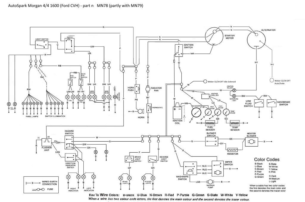
My attempt to document the AutoSpark loom MN78 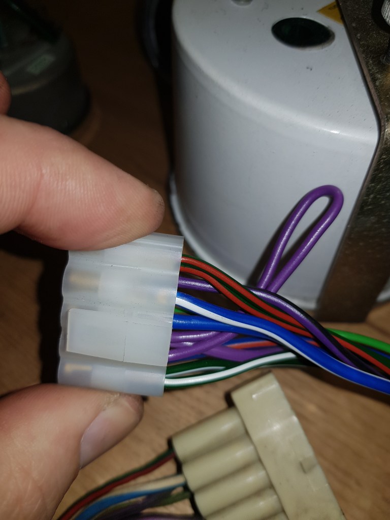
The purple loop is wrong. The indicator requires a black (negative) cable here. 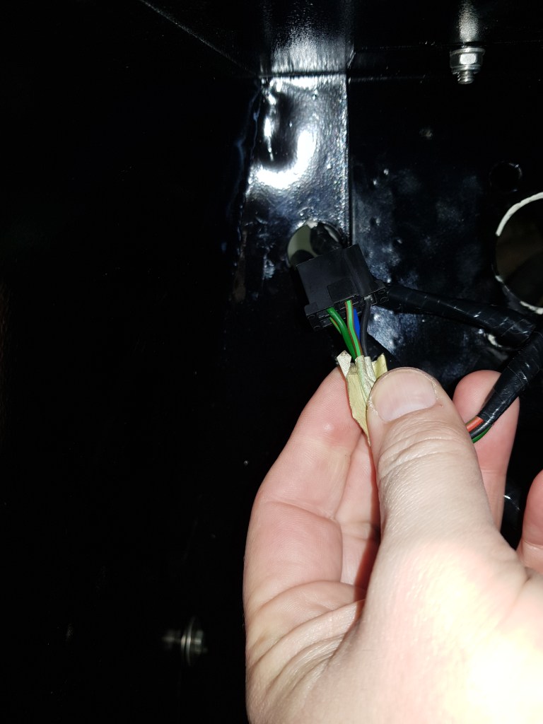
washer motor connector does not fit through the hole. My advice: if you order a new loom ask them NOT to put this on… but then again – I somehow got the old connector out???? 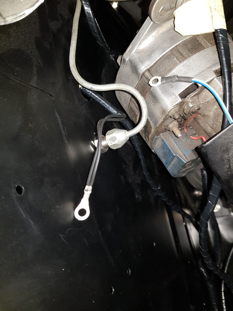
Tight fit – the old loom was about 1 inch longer on the left 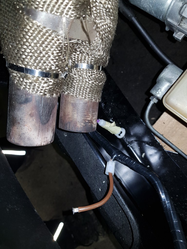
the worst place for a plastic inline fuse connector is beneath the exhaust manifold…. 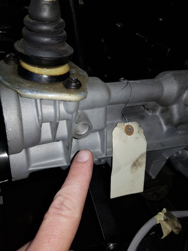
Just noticed that the reverse switch is missing 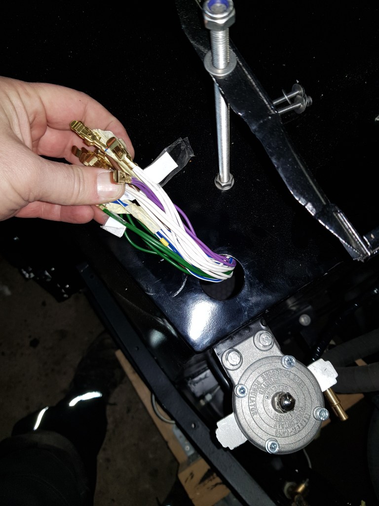
The cables are only long enough if I use the 4-way Lucas fuse box 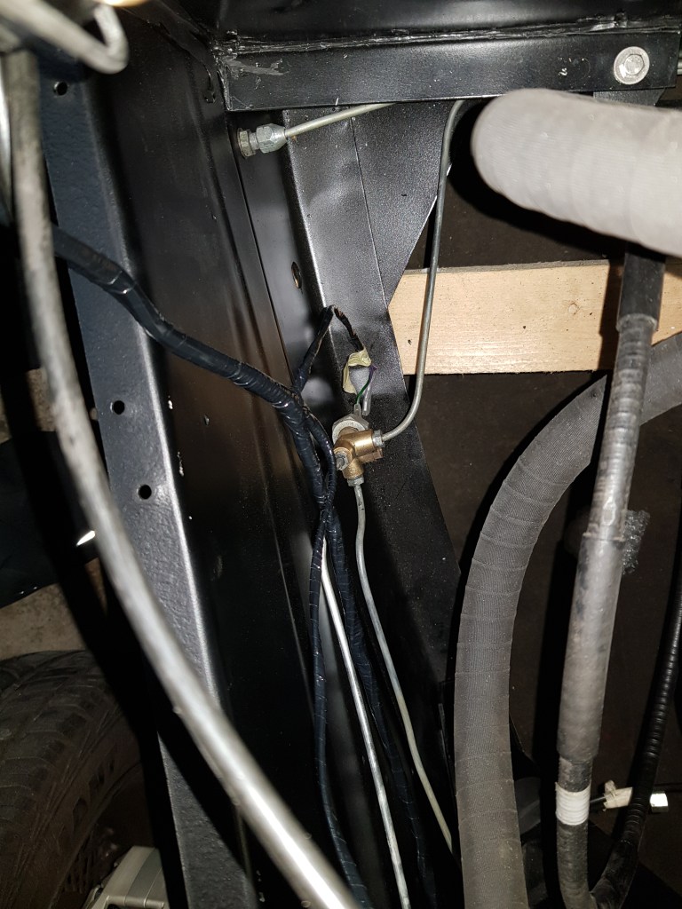
On the right side the loom could be 3 inches longer. 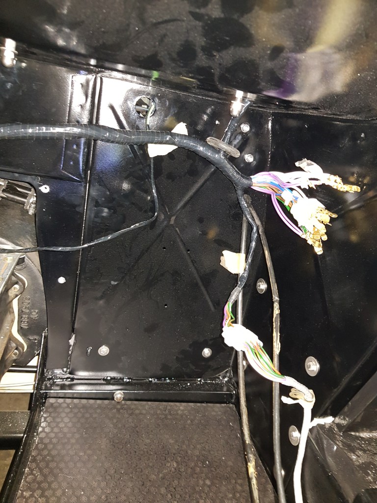
Testing to alternatively place the fuse box in the footwell 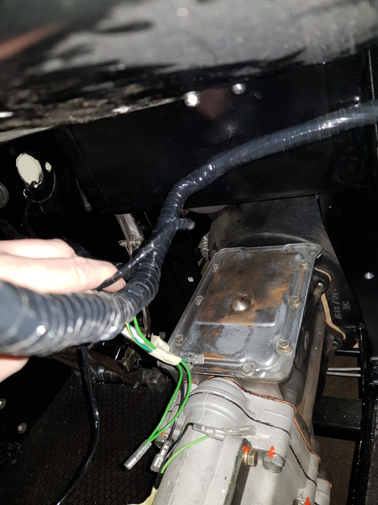
Need to install the blower unit next 
Alternator connector. Use small flat screwdriver to carefully get the cables out 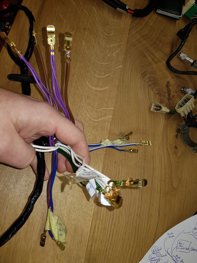
4 fuses only? If I connect them like this it would work…

Leave a comment