
My work on the Mini40 is done for now. After the required bodywork and painting is done (new sills, new door skins, some floor repairs) I will be reinstalling the dashboard and interior – but nothing extra-ordinary. The garage needs a good clean up next week before I will start with anything else. Well, the exception is the MGB wiring diagram and harness.
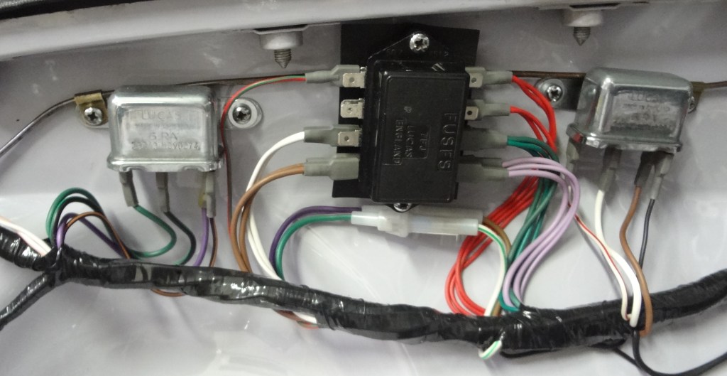
And I invested plenty of time in this plan. Some ideas were dropped, others fixed and some even tested. Unfortunately, I know that it is still not perfect nor done – but it is at a stage that allows me to continue to work on the harness now. The biggest change in my plan was (unintentionally) caused by a picture that was sent to me by Andreas. I understand that some people might say: “Hey, these are just some cables in some engine bay – no big deal”. And there might be even examples that are better than this. But it is really clean and neat while still sticking close to the original.
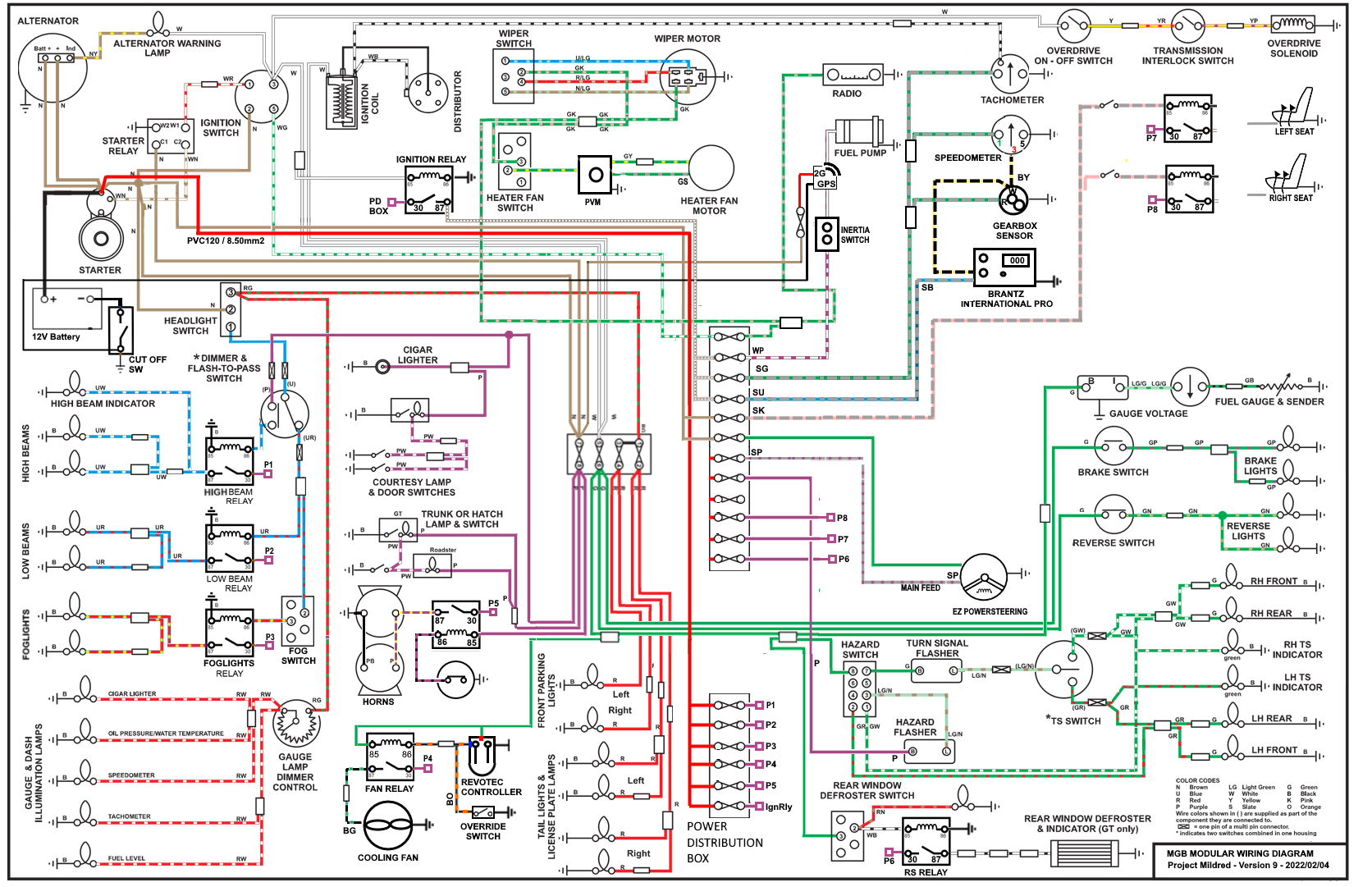
And after two sleepless nights I realized that my plan to add a big plastic fuse & relay box into the engine bay might not be the best. At least I don’t want to mount it as a replacement for the Lucas 7FJ box. In turn this resulted in more changes in the wiring diagram. And at this point I decided to go a step further and try to create a “modular MGB wiring diagram”. Something that allows to make the documentation of modifications a bit simpler and repeatable. For me it allowed the flexibility to play around with different fuse-box models, relays, and accessory options.
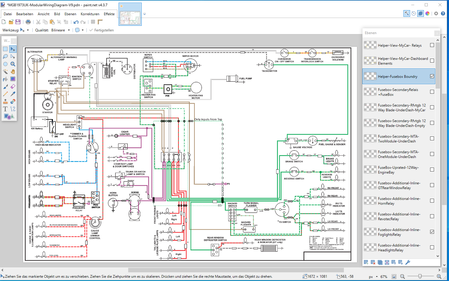
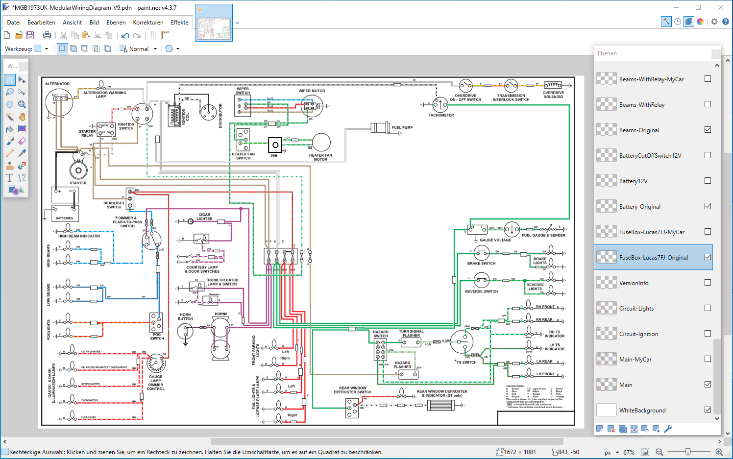
The design is roughly based on the AdvanceAutowire/Haynes plan for a 1973 UK MGB model. Even though there is professional software on the market – I went with a simple Paint.Net drawing instead. The software is free and accessible to anyone. There are versions for Windows, MacOS and Linux. Compare to other software it is relatively easy to use/learn. The native image format – called PDN – allows the use of layers.
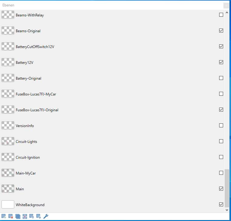
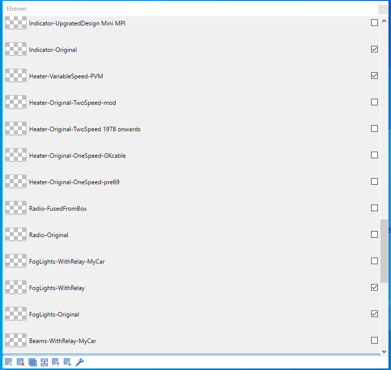
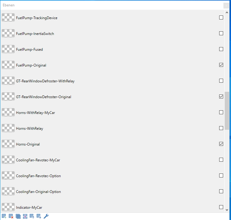
The canvas (so to say) is just a white background layer at the very bottom on the list. The “main” layer is like contains most components – just moved around slightly to create space in the center. Many layers follow for different components – either in their original wiring or for example with an added relay.
It is important to keep in mind that this is a schematic diagram. For my modifications, I duplicate a layer and add the extension “-MyCar” to the layer name. This makes it easy to check if everything is correct and revert changes. If you are interested in a copy of the PDN file – let me know.
With the change to the modular plan, I started with a simple version number scheme. In Version 9 of Mildred’s wiring plan, I am keeping the original Lucas 7FJ fuse-box. My goal is to have a clean, original look in the engine bay for the most part. The Starter relay will also stay where it is. But I have also decided to add relays for most components. This also results in many additional fuses and additional circuits. At least right now I am therefore planning a “Power Distribution Box” (similar to the late MPI Minis) in the engine bay.
Yes – this is not original, but I hope it will not be that noticeable if I mount it behind the brake servo. There are a couple reasons why I believe this is a good location. a) only a short additional power cable is required from the Starter Motor, b) the distance between the relays and devices that need them (head- and foglights, fan and horn) is also quite short.
I have ordered a new relay/fusebox holder as well as a kit for heated seats – which also made it to my list of options. The tracking device (see recent post) will be hidden in loom. A few modifications I am adding to the MGB will be added to the Morgan. Not an easy decision – but yes – I will remove the wiring harness from the Morgan again

Leave a comment