
This post must start with a warning/disclaimer. Everything I write here is just a random collection of ideas, decisions, leanings as well as opinions and experiences I gather as hobbyist while tinkering and restoring on some classic cars. Hopefully, this includes a few things that help you – the reader – to avoid the same mistakes I make along the way – or to get an inspiration.
This is especially true for all posts related to car wiring. After receiving feedback and opinions via various channels on modifying the Morgan and MGB wiring harness I want to make clear: I am not an expert in this area! Just someone that read some books and blogs, collected some experience on projects and maybe expose a bit too much of what others might not want to show.
To recap my older “all tangled up” post: When starting with the Morgan project back in April 2020 there were plenty of problems and undocumented changes not following any standard or major plan. And as my father is not able to tell me anymore what and why was done over 30 years – the plan was made early to get a new wiring harness. Even though I wanted to keep the wiring completely original – it was clear from this moment that I had to adapt my plan.
Switching out the Lucas fuse box was required and after testing a few cheap variants I ended up with one from MTA. In hindsight I regret not having added relays to several circuits back then. The benefit and importance (especially with old Lucas switches in the wooden dashboard) only became clear to me when starting to work on the 1973 MGB GT loom last year.
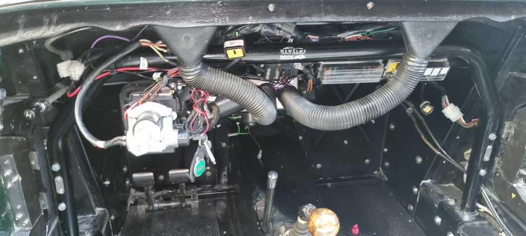
The fact that my Morgan is still “disconnected” is evidence that I underestimated the task. Or rather: the time, concentration and number of decisions that are required. As I did not want to drill more holes in the bulkhead for the additional MTA relay holder and power distribution box (PDB) – I bolted everything to two metals bars. The idea was that this would make it easier to mount the boxes later and help with cable routing.
A few people commented that this doesn’t look convincing. And when I tried to fit and tested everything (before wrapping the entire loom with tape) I came to the same conclusion. With the new under-scuttle-antiroll bar, the two metal bars brought the PDB too close. The cover touched the rollbar and the risk of a short circuit due to vibration was too high. And the slightly changed cable routing moved the entire loom about 5cm up on the bulkhead – which resulted that all connections in the engine bay were 5cm too short.
I removed everything and for days I tried to figure out a different approach without the PDB. One thing I did not want to change is to have a fuse for each relay. The issue how to best distribute the power from the two new brown (battery feed) cables in the fuse box buggered me the entire time. Although I could not find the source anymore, I remember a guidance not to splice battery feed cables. The MTA fuse box does not have a bus connector for multiple fuses.
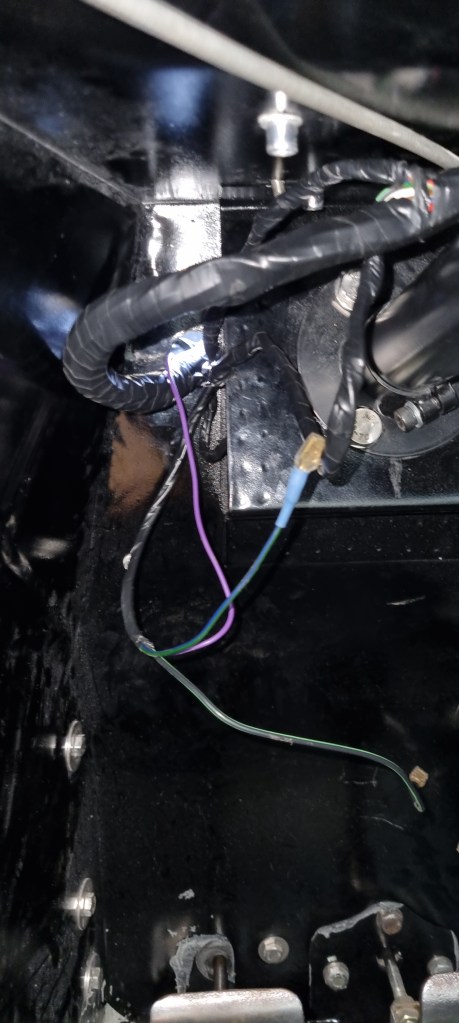
Last week I decided to bite the bullet and drill additional holes into the bulkhead for the MTA relay holder as well as the PDB. With these directly attached, the cable routing moves down 5cm again – fixing the biggest problem. The trial fitting last week went well and revealed two minor issues. Number one was that the Lucas stalk horn switch is switched on the earth side. This mean that the relay port 86 needs a purple feed instead of an earth connection. The other problem was that the fuse for the power steering circuit requires a 15A fuse – the 5A fuse I had blew right away.
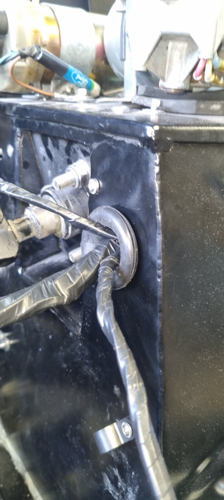
After taking the entire loom out again I started wrapping everything with electrical tape. I stopped counting how many times I fitted and removed the entire loom since I started the project. But the result is that it just takes about 90 minutes now to put everything back it. A few more fixes and tasks need to be completed tomorrow. I sincerly hope to do a test drive tomorrow. Fingers crossed.
https://wordpress.com/post/fixingc6622.wordpress.com/2599


Leave a comment