")
A few weeks back, on a cold December night, I got out the box with the new wiring loom I started last year. As Mildred is intended as daily driver, a number of additional features will be added. This requires modifications to the standard wiring harness. While I started off from a 1973 MGB UK based loom, small changes of the late 1978 wiring as well as a number of relays were the basis for the diagram I did 2023. In that last two years I also helped quite a few other people with smaller electrical issues on British cars. I feel comfortable as soon as it is BSAU7 based. Some were MGBs but I also had Rover based MPI Minis, a Defender 90 and recently supported remotely on a MG RV8 wiring issue. All Rover electrical diagrams share similarities and introduced improvements – which I kind of like.
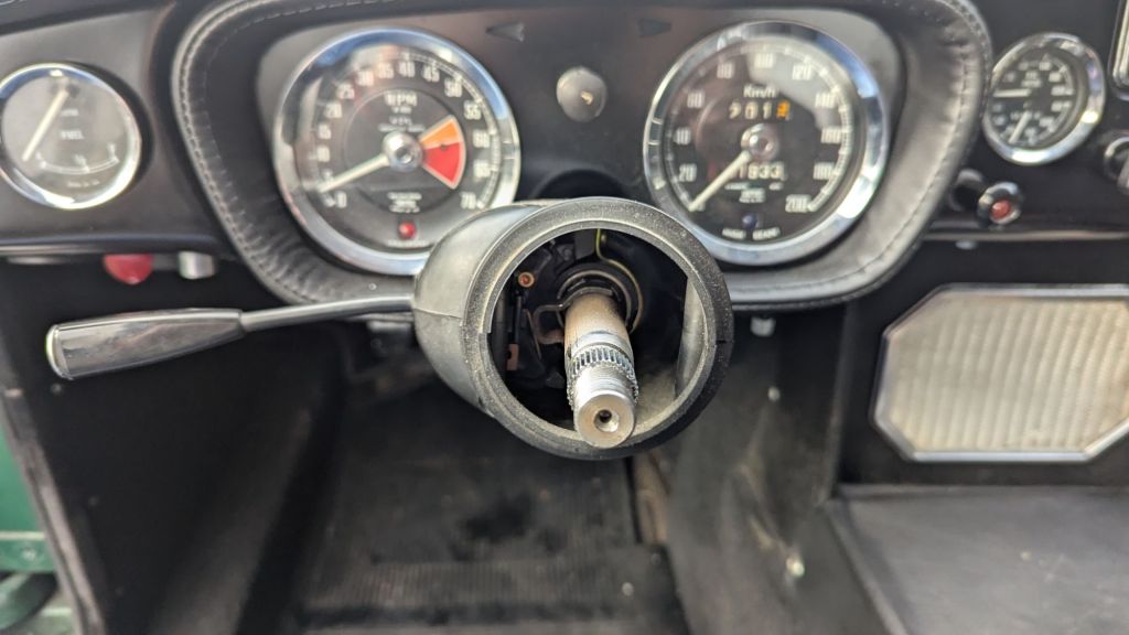
For daily use, but also for Endurance Rallyes like the Lejog, having a wiper stalk control mounted to the steering column is beneficial. The Lucas toggle switch on the dashboard of the 1967 MGB GT might be period correct – but annoying if you have to use it often. Having Intermittent wiper functions is also high on my wish-list. For this I tested standard relay 19 back in 2023, which I didn’t like. From the Saab 900 I borrowed a Standard Bosch relay 99 (which is also still available on AutoDoc). This worked but raised the question on how to control it? The idea to use the Rover 200 column stalks and part of their wiring (the same or very similar ones to the MG RV8) came to my mind. A used pair I got the junkyard quickly made clear that this is not very practical. Size and looks didn’t fit. And to be honest – wiring it up turned out to be more complex. Additionally, while playing around with this, I also found a great alternative for the Intermittent controls in Konrad Stucki’s WIM2405 Modul. More on this later.
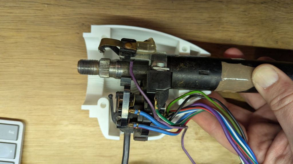
On MGBs wiper stalks (part no. 37H2678) were introduced in the US from 1968. In some EU models this change followed later from 1971. With the introduction of the “1974.5” variant all MGBs got them. The model change in June 1976 replaced the stalks with the AAU4995 Indicator (LHD) and Lucas BAU1022 wiper stalk. The RHD drive models have the indicator and wiper stalks side switched. They use AAU4491 and BAU1020. Coincidentally, I got my hands on an AAU4491 indicator stalk (which was attached to a 1978 wiring loom I bought for study purposes at some point). And I think this is a great fit.
So, next we need to look at the different MGB steering columns and see how to make this fit. An excellent source of information is MGB-stuff.org.uk. It helped me to understand the Type3 and 4 differences for indicator cancellation – this will be important later. But the site does not mention the outer diameter of the different columns. As far as I could research it there are at least five(+2) different types. In my spare part collection I have three different types. The late collapsible 4cyl model has the part number BHH1856. The MGB V8 had a similar model BHH1596 – which is a bit shorter with 720mm total length. The newer AAAU4995 stalk mounts to those and the diameter (at the point where the stalk is mounted is about 35mm (or 1-3/8inch)
Mildred’s new body shell is from 1970. It lacks the required mounting brackets for the newer types steering column. It is designed for the earlier type of collapsible variant BHH515. The outer diameter is slightly smaller with 1- 1/4inch (~32mm). Before 1968 the non-collapsible variants 17H6577 and 37H4768 existed. These seem to also have been available with steering lock (7H6972 and 37H4767). While I am not 100% sure if the old one from my 1967 MGB GT is actually original – I believe it to be 37H4768. It also has 1-1/4inch in outer diameter.
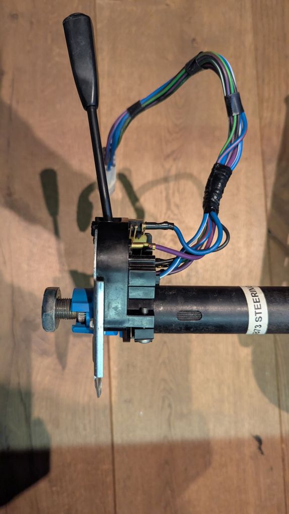
BTW: They are all 782mm total length, have 48 splines with a length of 19mm at the bottom and 36 splines with a 17.5mm length for the steering wheel. From what I read the very early columns have the same 48×19 splines at the bottom and the steering wheel.
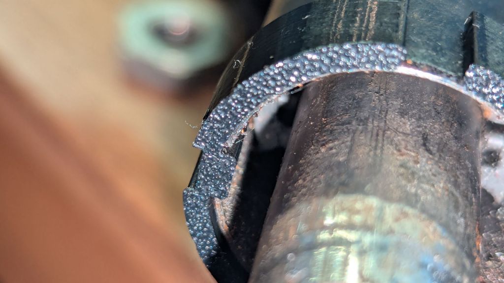
Bottom line: the late AAU4491 indicator/wiper will not fit the early steering column. But this is a 10 minute fix with a 3D printer. I quickly designed a spacing adaptor in Freecad, printed it in PETG and was able to attach it to both – the BHH515 as well as the EZPowersteering on my 1967 MGB GT.
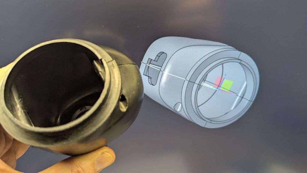
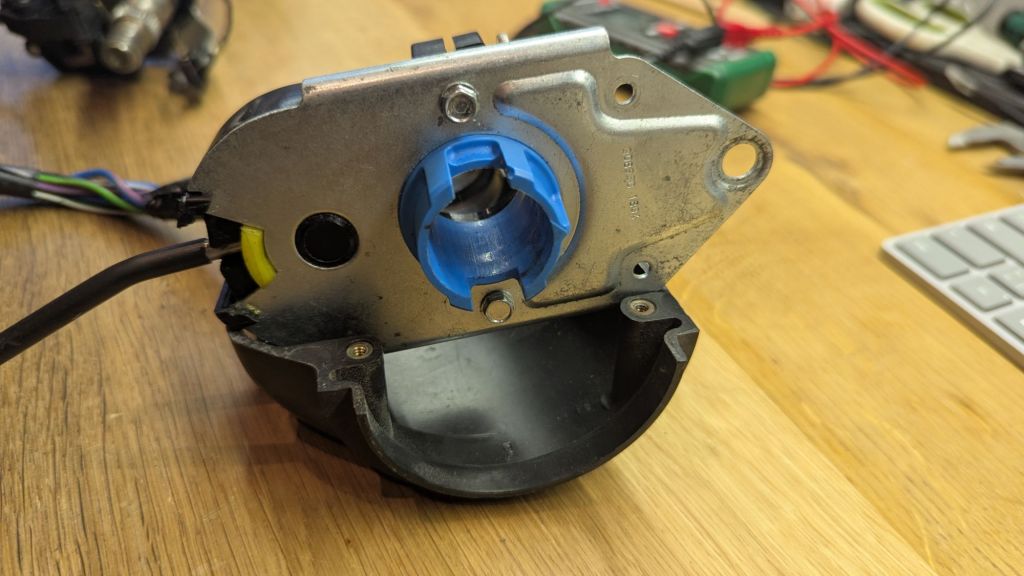
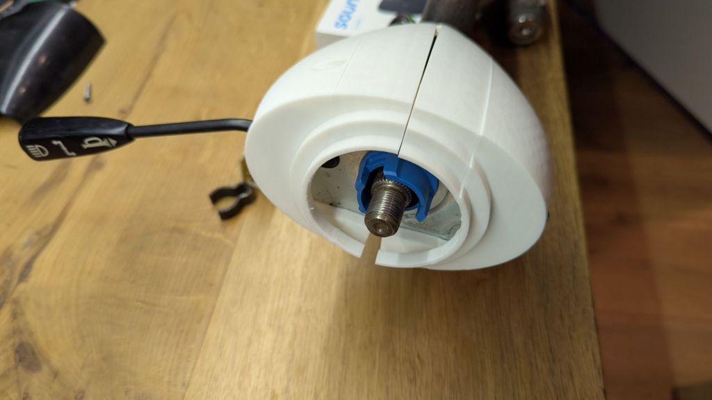
Of course this automatically brings up the next challenge: Which cowl will fit this setup to cover the stalk? The late MGBs had a different dashboard. This had a much larger cutout for the cowl. An item hard to find nowadays. Thankfully, Kevin Wells made a copy of two variants and shares the STL files for 3D printing on this site and here. Kudos to him. I downloaded the files. Then, I started thinking on how to put a square peg (more or less) into a round hole. The early dashboard is quite different. It has a small cutout (rounded on the top) for the steering column. The early cowl (18G8713 for RHD and 18G8714 for LHD) is also much smaller and – at least in my opinion – more elegant . But it was never designed for a wiper stalk. And because it has a top and a bottom half, it is also not possible to somehow combine the LHD and RHD. Besides, AAU4991 (or AAU4995) are a bit wider.
Important: 18G8713/18G8714 are available for two different stalks: The early variant BHA4628 (used in GHN/GHD3+4 cars) and BHA4948 (used von GHD/GHN5). The early ones did not have the flash headlight flasher function. Also the cutout in the cowl for the stalk is different.
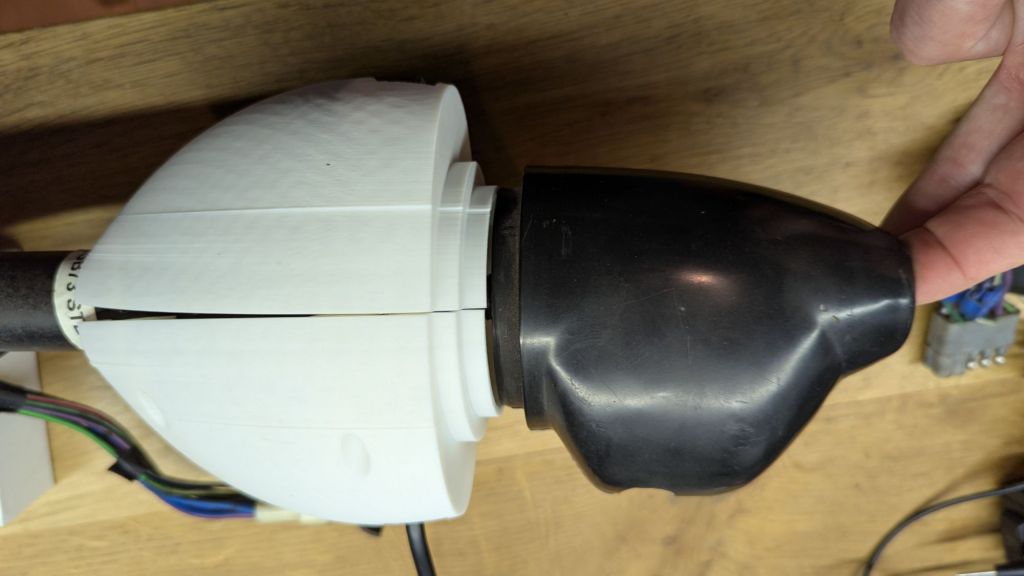
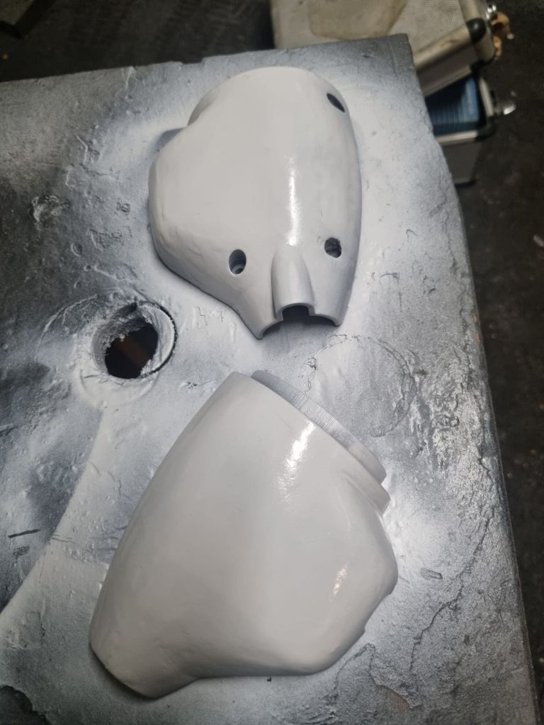
I decided to make my own. While I learned a few things in Freecad last year, I am still a bloody beginner. Slowly, I am getting better with on dependencies between objects. I assume that most beginners struggle with this like I did. It really helps to break down objects into simple structures first, make sure to remember or mark reference points/sketches/objects and then go into designing details. But as soon as more complex forms, revolutions, lofts or additive pipes are required – things can become rather challenging. Designing a cowl based or similar to the original design, but for the newer indicator was a quite learning curve. My son told me to switch to Fusion360 or Solidworks a couple times now. While I think he is right, I decided to investigate how to do it in Freecad anyway. And this excellent tutorial on Youtube helped me quite a bit. OK – installing the curves workbench manually, working around issues to add supporting rips and finding a good system to do changes – that was all not included in the video.
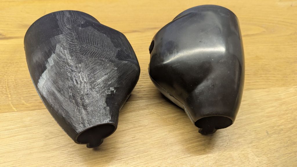
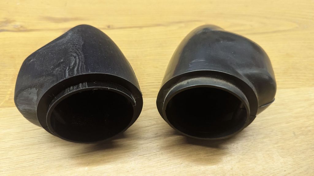
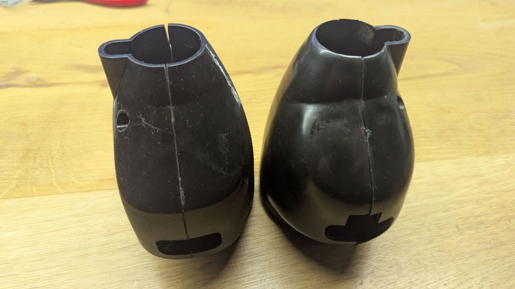
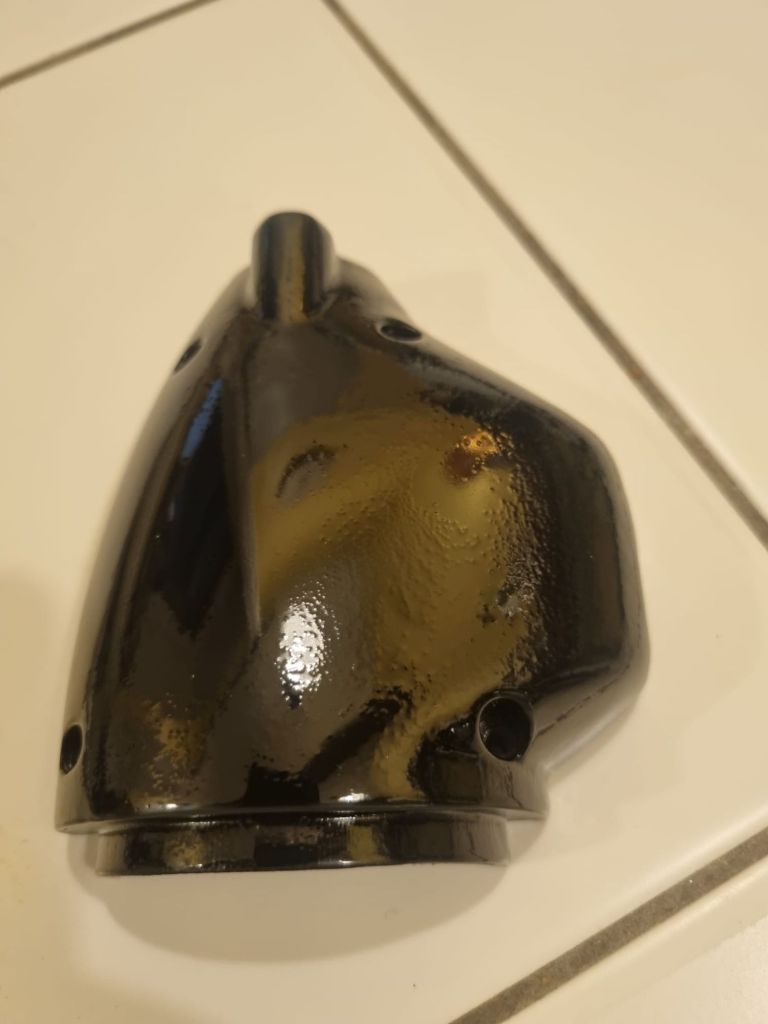
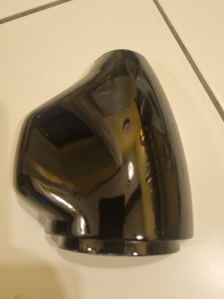
But eventually I got there after a few hours. On the pictures you see my first attempt. (still in white PLA). Warping was an issue caused by the design – but can be mitigated to some extend. Even in draft mode setting and only 15% infill the prints are really strong due to the curved design. Actually much better than the original plastic (ABS?). Talking about the original – I decided to design the 18G8713/18G8714 variant as well. Marc – a fellow MGB driver – was so kind to try and test fit and paint one of the first “semi-final” version. Pictures below. I will incorporate his feedback and will switch to M3 screws and inserts (I used M4 20mm screws in my initial design)
I will upload 3MF files for the LHD and RHD versions on Makerworld


Always good to read what you have been up to with Mildred recently Tim, thanks!
LikeLike