
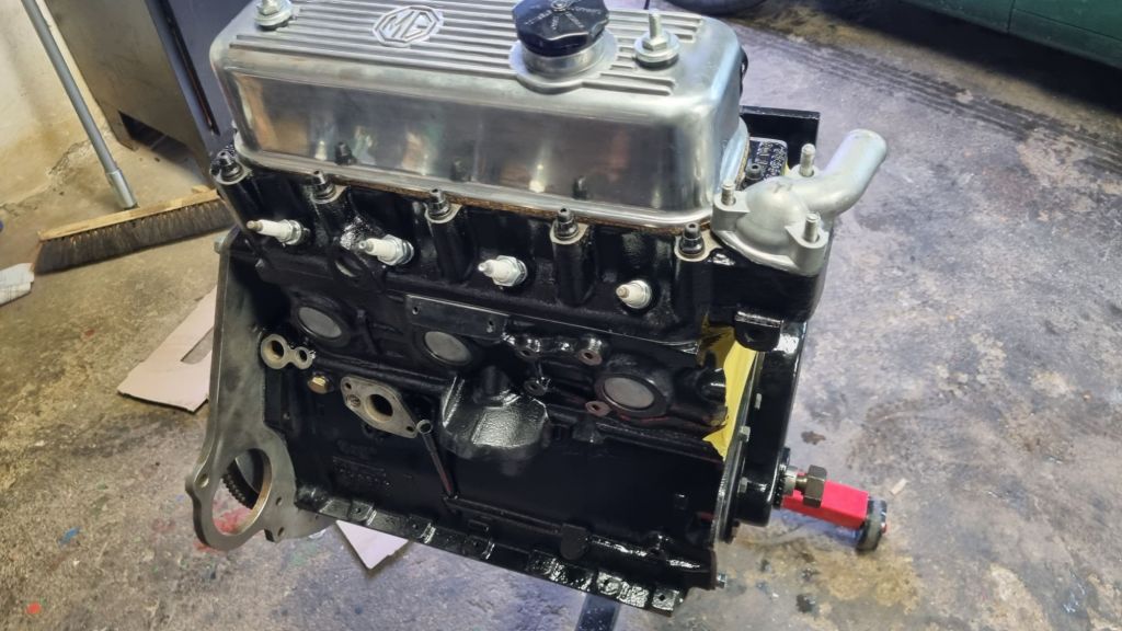
This full post is going to be a long read. The TLDR summary is: After a number of problems the engine is about 85% complete. A few parts need to be changed and ordered – a first test firing might be still a few weeks away. But if you want all details you need to read on.
The last article and update I wrote was in late December last year. At this point I got my engine part back from GB Classic in Cologne. As it turned out they gave me a different crankshaft that was not even machined (although this was what I paid for). By the end of January 2025, I finally had the right crankshaft back. They used their right to correct the mistake – which meant I had to give them the crankshaft again.
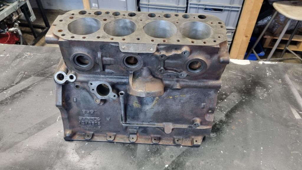
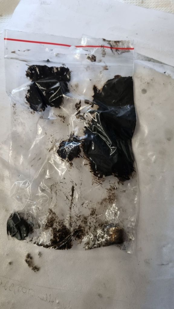
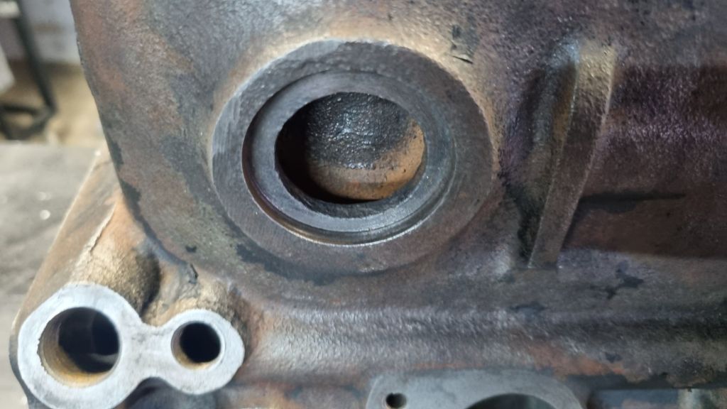
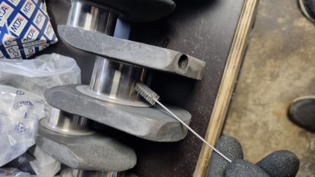
The engine block was bored out – but the oil gallery plugs were not drilled out as originally discussed. This is strongly recommended in Peter Burgess’s book “How to Power Tune MGB 4-Cylinder Engines”. So, I handed the block to KS Motortechnik in Bonn and they took over this job. There is a good overview with pictures on the plug locations at the MG Experience forum. The oil galleries were clogged up with old oil gunk.
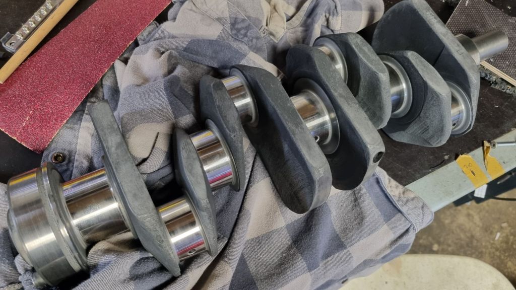
After waiting for another four months, I was able to pick up my – now overhauled – crankshaft in Cologne last Tuesday morning. As I learned from discussions, a good machine shop will either get and hand-over the correct bearings or at least the measuring’s of their work. I asked for this in advance via email. But like last year – I got no reply from GB Classic on this. We did agree on a pickup date and time via WhatsApp however. As paying customer, my expectation was to at least get a few minutes of attention and a proper handover with the information on the required bearings. Instead, I was left without any useable information and the owner turned to another project within two minutes after showing me my crankshaft.
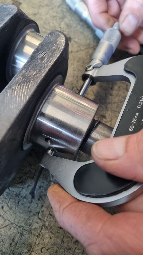
As the only possible date to do the engine rebuild with Michael in the next couple of months was last weekend – I had to get the information on the bearing size quickly. The only option was to head straight to KS Motortechnik. I arrive at lunch time. The owner was on vacation and the guys working there busy. But I was lucky and one of them offered to do the measurements of the crankshaft anyway. Doing this with a micrometer means measuring four different points per journal. This takes some time to do it – so I left the crankshaft with them.
Back at home I received a WhatsApp from Cologne that the required bearings are 0.010″ undersize. As ordering the ACL bearings was the priority – I went ahead with this information and called Cambridge Motorsport. There were super friendly and helpful. Jon on the phone suggested an DHL Express delivery. This would arrive intime by Friday.
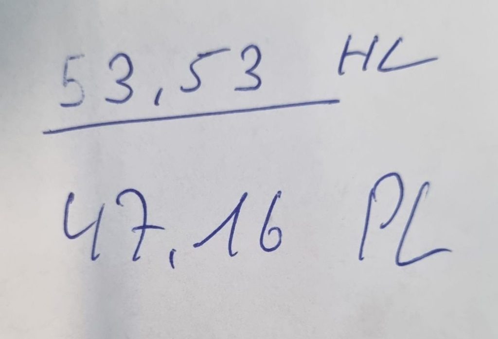
About two hours later I got the measurements from KS Motortechnik. The main journals are all have a size of 53.53mm – the crankspins measured at 47.16mm. At least according to the specs in the workshop manual I thought that this is a problem. The main journal has a standard size of 54.01mm to 54.02mm. The first undersize of 0.010″ is 0.254mm less. Second undersize is – 0.508mm. Adding diametrical clearance – I thought we need to have a value of around 53.50mm. All this aside – one thing was clear: The 0.010″ bearings that just found their way into a DHL Express truck are most likely the wrong size.
I posted a question in the MGDC forum. But the answers I got were not really helpful. Except that Darius mentioned that measuring the journals only is not sufficient. We need to measure the bearings in the block torqured down without a crankshaft. Michael and I discussed the best way forward. If GB Classic says 0.010″ this should be correct and we should start with these bearings. Or should we postpone our planned engine rebuild and have a machine shop confirm everything? We agreed that the best way forward now is to also get 0.020″ bearings. If 0.010″ has too much clearance – we will measure the 0.020″ bearings. My only option for this was to drive to Limora and take whatever brand of bearing they have. This turned out to be a set of standard King bearings.
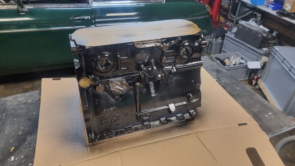
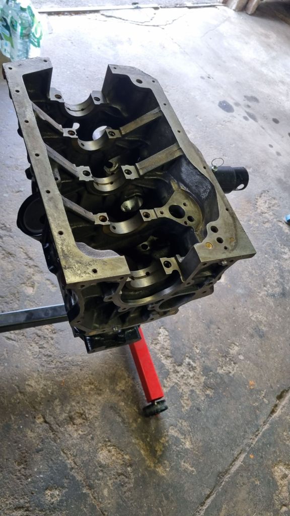
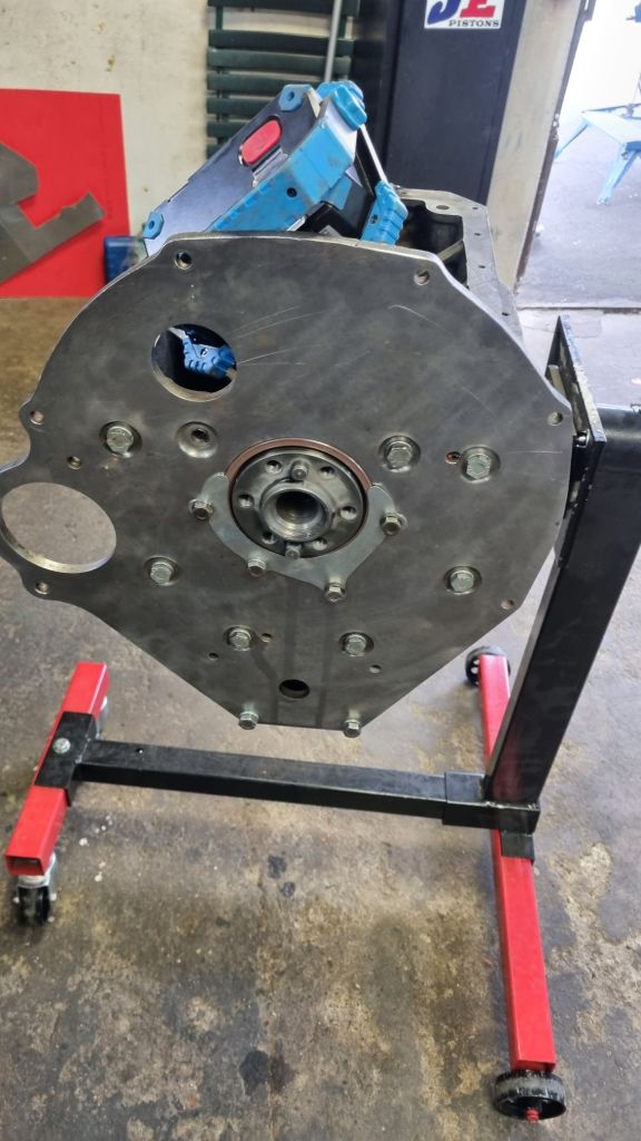
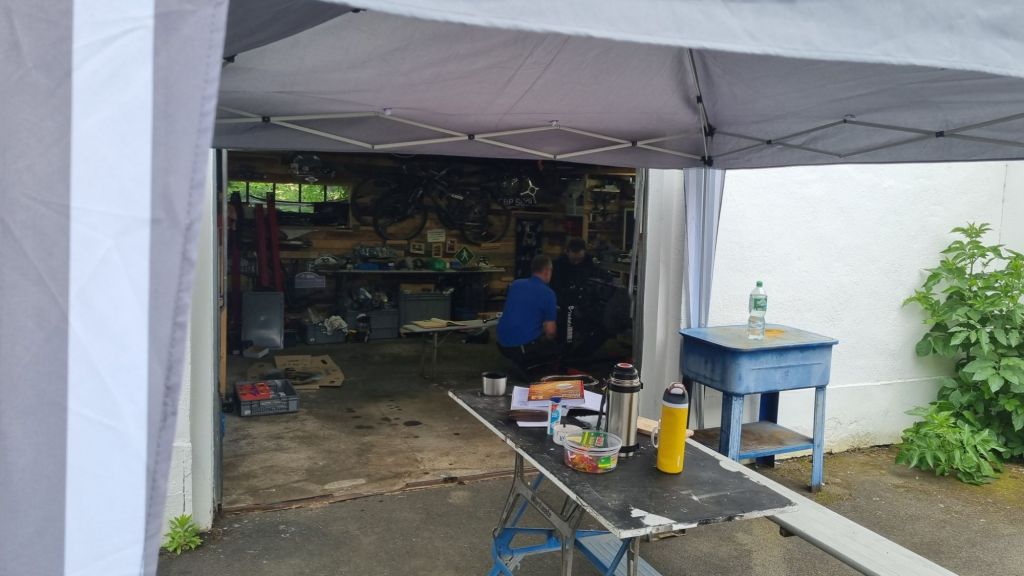
Back in my garage I prepared everything for the weekend. An additional table with all parts laid out in the rebuild sequence was setup. The engine block and crankshaft were cleaned another time. Last step was to apply five coats of paint to the block. The DHL Express package from the UK arrived just intime on Friday morning. Michael arrived about lunch time, and we got straight to work. It only took a few minutes to confirm that the GB Classic’s specified 0.010″ bearings cannot be right. After torquing down the block – you could move the crankshaft to show the play. I really felt I should get a statement from GB Classic on this – but of course the owner did not answer my phone call as usual. But why waste more time with this unprofessional shop? Let’s move on.
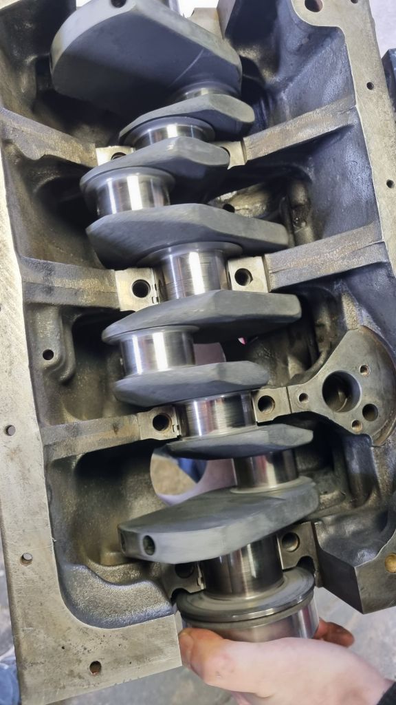
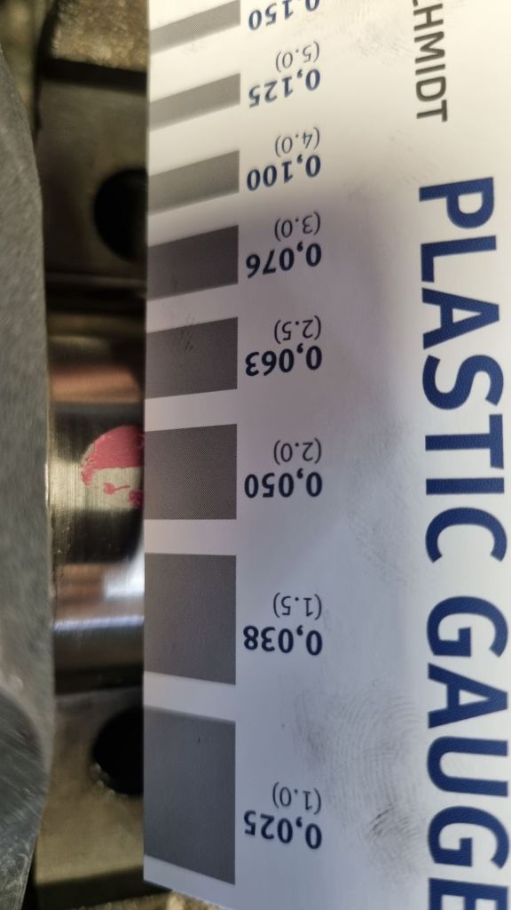
With the 0.020″ bearings in the block, we decided to use plastic gauge to check if we have the right clearance. And despite my concerns with the measurements of the crankshaft journals, I turned out that the results looked promising. A diametrical clearance between 0.0254mm and 0.068 is within the specifications. We got around 0.040 and 0.050mm – quite good. After removing the plastic gauge, the bearings were installed with Penrite Assembly lube and torqued down. It was possible to turn the crankshaft with a bit of pressure on the wrench via the pulley bolt. At this time Henrik stopped by and supported us as well. He also has done rebuild a few engines and it was great to have him as support as well.
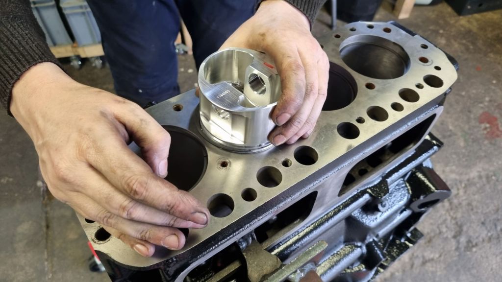
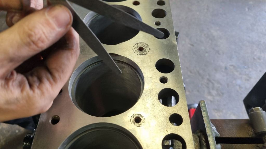
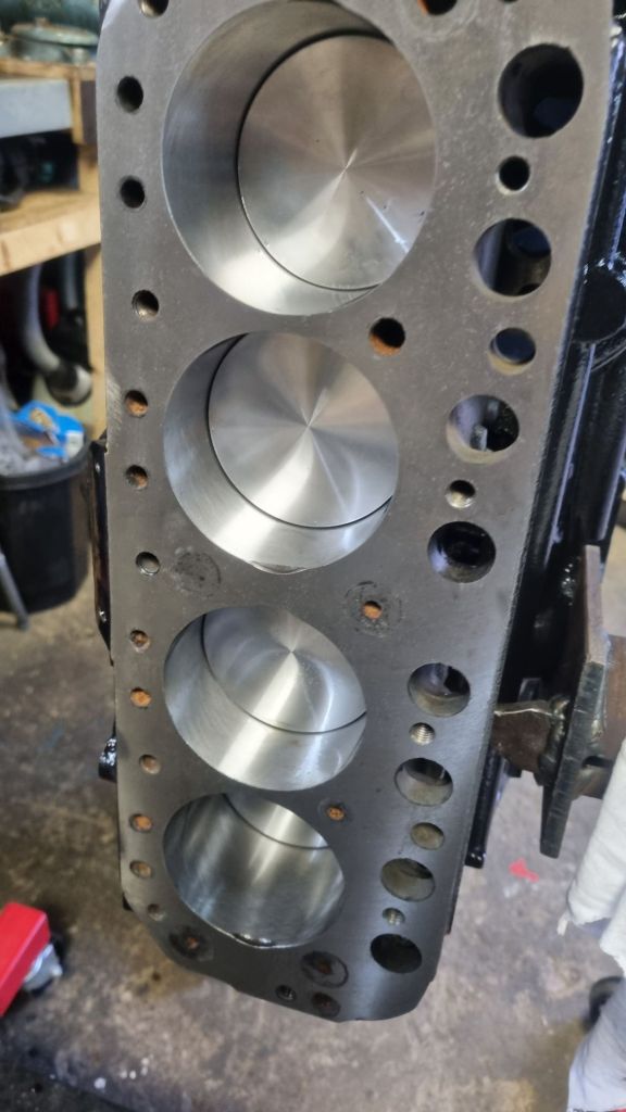
Next up were fitting the JE pistons with the Maxxpeeding conrods. The supplied floating pin fits perfectly on the piston – but the conrod piston bushings required adjustment. They have an oil channel and reaming the bush out, results in having less depth in this channel. Luckily, we only needed to take over a very slight amount. Still – this concerns me a little. All piston ring gaps were spot on – we did not have to modify one of them. The ARP bolts supplied with the conrods need a 12-point socket – which I bought a while ago as part of the preparation for the rebuild. After fitting the front plate we left the garage and called it a day.
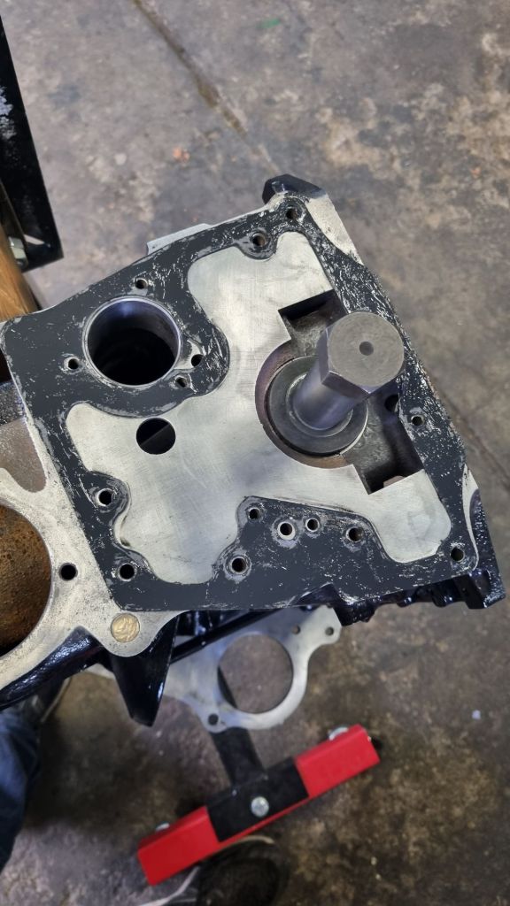
We started early on Saturday morning. Before installing the camshaft, the engine backplate had to go one. Another clean wipe of the new cam bearings followed before it was carefully inserted with assembly lube. Fitting the Piper Vernier Duplex Kit crankshaft gear required slightly filing down the key. Once all this was done we were able to start the task I have not done so far: measuring and setting the camshaft timing. Years ago I helped rebuilding a standard Mini A-series engine. All we did is make sure to align the dots on the two gears – we did know or bothered with timing. This engine ran great. For Mildred’s engine however, I went with the Piper HR270 cam which I got along with the cylinder head from Peter Burgess. The values for this cam are in this book – along with the instruction on how to do the timing.
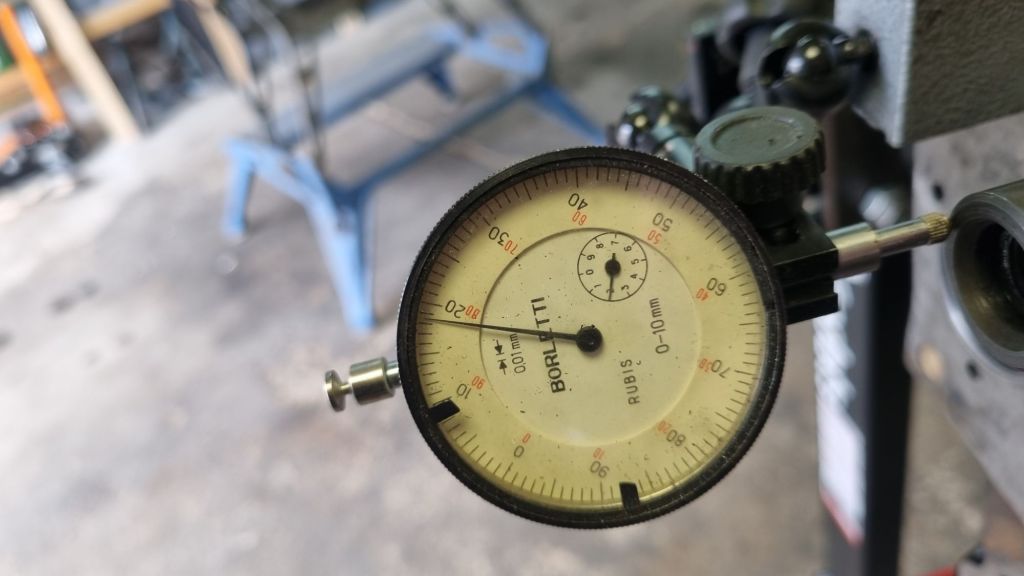
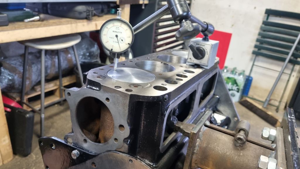
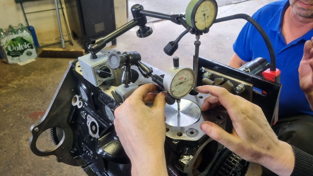
Michael brought along the Moss timing disc and this first job is to determine the right TDC. This is done by measuring the height of cylinder one. The crankshaft needs to be turned for this back and forward – which is best done via the flywheel. At this point I noticed that I don’t have the ARP bolts for the shiny new Fidanza Aluminum flywheel. So, the old bolts had to go one temporality Finding TDC required checking the degrees shown on the timing disk 0.025mm before and after the initially set TDC. We triple checked this before we moved on to the camshaft. The procedure is similar – but you measing the height on the push rod for the first intake value. The cam has full lift at 108° ATDC. Our first measurement was about 5° off. This is where the adjustable Vernier comes in handy. With the vernier screws slackened the required change is carefully done by turning the crankshaft. The camshaft will not turn. After the offset is adjusted on the crankshaft side – the Vernier screws are tightened again.
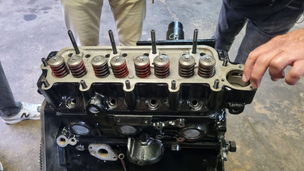
After this is done the, all measurements are checked again. As we tried to do this as good as possible – doubling checking our work – the entire procedure took us a few hours. While I quicky drove off to get lunch for us – Henrik and Michael cleaned up the workbench and oiled the new CF04 cam followers. Michael finished lunch quickly and at 3pm the oilpump and distributor drive where also in place. With a few members of the local MG group stopping by at my garage for a drink – we installed the new ARP head studs, the Payen AK660 gasket and the overhauled cylinder head. Questions came up when I unwrapped the overhauled rocker assembly I got from Peter Burgess. Henrik said that thin 0.005″ shims are required. I remembered that I included those in the bag – but they were missing now. We also have different opinion on the location. Henrik says they goes beneath the other rocker assembly posts. And this is also written in Peter Burgess book. I removed mine from the centre ones. And 12H3960 is listed on most webstores as Centre Pillar shim?! We need to ask the community on this one.
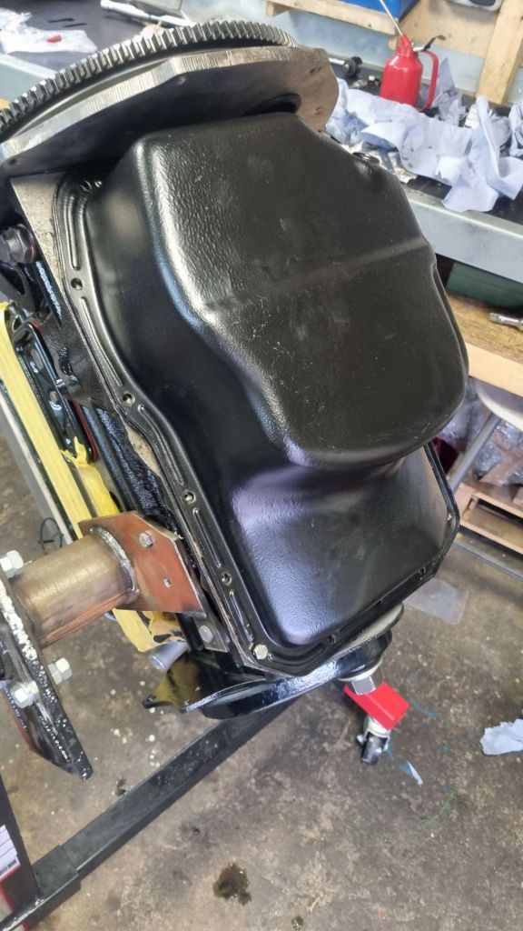
Anyhow, without those shims we could not finish the top part of the engine. We decided to wrap up and get dinner at an Irish pub close by. It was awesome to work with a like-minded people together at my garage. For the last seven years I have usually worked alone at my garage. This was great fun, and the engine rebuild is on a good way now. On Sunday I just wanted to install the oil sump, Water pump and a few other small bits. It was then I discovered a problem. The oil sump interfered with the new ARP nuts. A quick search surfaced this old forum post on the topic.
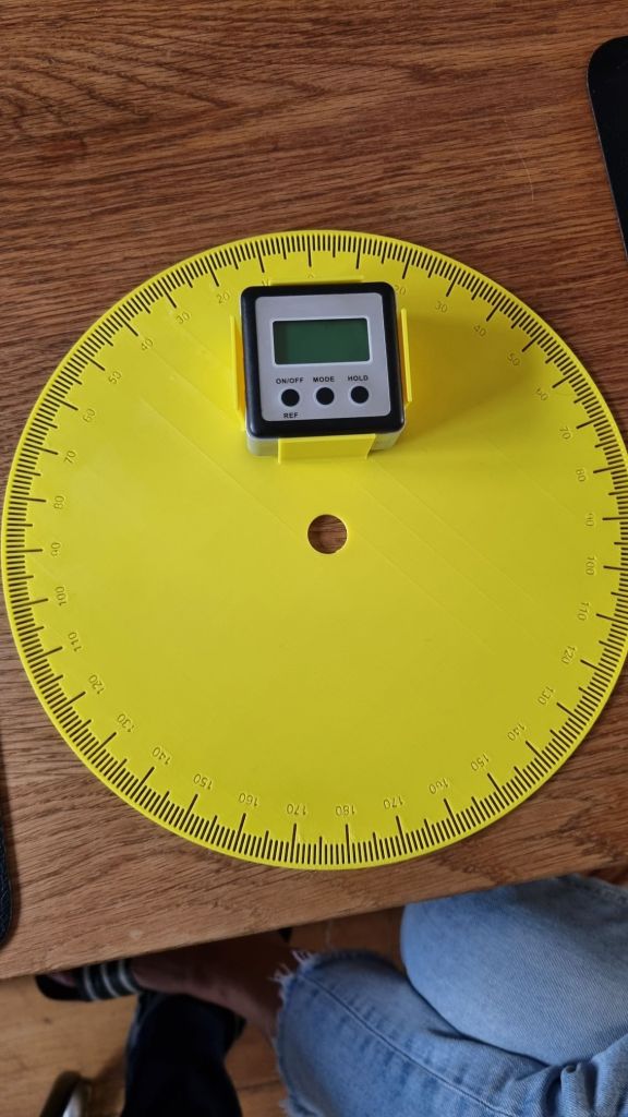
I ordered ARP main bearing studs kit (ARP 206-5403). This is correct for the 18GB engine – my 18V581 however required the ARP main bearing bolt kit (ARP 206-5002!!) however. As two of the old bolts have significant wear signs on the threads – I am not going to reuse them. It will take a few days until the new set arrives. This gave me time to design my own timing disc and print it on my 3D printer. But Freecad would crash my computer when I tried to add 360 degree markers as objects. My son has a better computer and software – and is much better in CAD than I am. A few minutes later I had the right STP file. I added a holder for a digital angle gauge. Will test this out in a few days and practice measuring on my engine again.

Goodness, WHAT a bunch of unprofessional people!!!
LikeLiked by 1 person